No edit summary |
No edit summary |
||
| (25 intermediate revisions by 9 users not shown) | |||
| Line 1: | Line 1: | ||
{{Maintitle | |||
| logo = Im-aim.png | |||
| maintitle = First Steps: {{PAGENAME}} | |||
}} | |||
{{NavigationTop-Tut3 | |||
| LinkBackwards = Lesson_3_Tut3 | |||
| TextBackwards = Lesson 3 | |||
| LinkForwards = Lesson_5_Tut3 | |||
| TextForwards = Lesson 5 | |||
}} | |||
==Overview== | ==Overview== | ||
This lesson introduces into the | This lesson introduces into the stage view panel - a minimal 2D visualization tool which offers valuable support for programming your show. | ||
==Lecture 4: The Live View (Stage View) == | |||
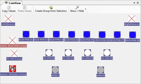
The '''Stage View''' is one of the several tools in the tool menu. When you create devices and/or groups, some (interactive) icons are automatically generated in the '''Stage View'''. You can move these icons to any place you want by dragging them with the mouse. In this way you can model your stage in 2D representation. | |||
It could be helpful to load a background picture for better mapping your stage. Click on the background with right mouse button and choose "Edit Background". Additional background pictures can be inserted in the folder ".../DMMXControl3.0/Kernel/Pictures". | |||
It is possible to create several '''Stage View''' panels that are administrated with the '''Project Explorer'''. In this way you can split your devices or map different locations for your show. | |||
To add devices or device groups in a '''Stage View''', let's move into the '''Project Explorer''' and drag&drop units into the respective '''Stage View'''. In the current betaversion it is not possible to drag&drop a device from the devices branch directly into the '''Live View''' window. Move it within the directory tree instead. | |||
{{Picture_with_subtitle|DMXC3L04 liveView.JPG|1|The stage view|center|600px}} | |||
The '''Stage View''' distinguishes between "single lamp" icons and "group" icons. If you select an group icon all following operational actions are applied to each group member item. | |||
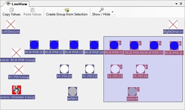
You can select a set of devices by drawing a frame around them (this is a kind of temporary group - please do not confuse this with the default groups) or by single selection holding the '''CTRL''' key. Marking such a set of devices can also be helpful for positioning the icons. With the "create group" button you can define permanent groups from the selection. | |||
There are some helpful shortcuts helping to improve the assignment of icons in the '''Live View''' (moving and alignment of symbols). At first you have to select the device icons by drawing a frame or pressing the '''CTRL''' key (windows style selection). | |||
{| class="wikitable" | |||
|- | |||
! key !! action !! result | |||
|- | |||
| M ("Matrix") || press key M and drag mouse || a matrix is created from the selected icons | |||
|- | |||
| F ("Fanning") || press key F and drag mouse || icons are proportionally aligned (e.g. in a row) | |||
|- | |||
| C ("Circle") || press key C and drag mouse || icons are aligned in shape of circle | |||
|} | |||
{{Picture_with_subtitle|DMXC3L04 liveView groups.jpg|2|Groupselection of different fixtures|center|600px}} | |||
By using the '''Show/Hide''' button you can choose which attributes are displayed near the icons (device name, selection number, intensity, ...). | |||
==Exercise== | |||
1) Try to generate the same layout in the live view panel as shown above by shifting the icons | |||
<br> | |||
2) Mark a subset of devices and align an operation with the '''property panels''' (First, press the '''Lumos''' button in the '''intensity panel''' to open shutter/dim up lamp) | |||
{{NavigationTop-Tut3 | |||
{{ | | LinkBackwards = Lesson_3_Tut3 | ||
| TextBackwards = Lesson 3 | |||
| LinkForwards = Lesson_5_Tut3 | |||
| TextForwards = Lesson 5 | |||
}} | |||
[[de:Lektion_4_Tut3]] | |||
[[Category: Tutorials DMXControl 3]] | |||
Latest revision as of 08:46, 15 May 2013
| [[File:{{{Logo}}}|48px|link=]] | {{{Pagetitle}}} |
Overview
This lesson introduces into the stage view panel - a minimal 2D visualization tool which offers valuable support for programming your show.
Lecture 4: The Live View (Stage View)
The Stage View is one of the several tools in the tool menu. When you create devices and/or groups, some (interactive) icons are automatically generated in the Stage View. You can move these icons to any place you want by dragging them with the mouse. In this way you can model your stage in 2D representation.
It could be helpful to load a background picture for better mapping your stage. Click on the background with right mouse button and choose "Edit Background". Additional background pictures can be inserted in the folder ".../DMMXControl3.0/Kernel/Pictures".
It is possible to create several Stage View panels that are administrated with the Project Explorer. In this way you can split your devices or map different locations for your show.
To add devices or device groups in a Stage View, let's move into the Project Explorer and drag&drop units into the respective Stage View. In the current betaversion it is not possible to drag&drop a device from the devices branch directly into the Live View window. Move it within the directory tree instead.

|
| Picture 1: The stage view |
The Stage View distinguishes between "single lamp" icons and "group" icons. If you select an group icon all following operational actions are applied to each group member item.
You can select a set of devices by drawing a frame around them (this is a kind of temporary group - please do not confuse this with the default groups) or by single selection holding the CTRL key. Marking such a set of devices can also be helpful for positioning the icons. With the "create group" button you can define permanent groups from the selection.
There are some helpful shortcuts helping to improve the assignment of icons in the Live View (moving and alignment of symbols). At first you have to select the device icons by drawing a frame or pressing the CTRL key (windows style selection).
| key | action | result |
|---|---|---|
| M ("Matrix") | press key M and drag mouse | a matrix is created from the selected icons |
| F ("Fanning") | press key F and drag mouse | icons are proportionally aligned (e.g. in a row) |
| C ("Circle") | press key C and drag mouse | icons are aligned in shape of circle |

|
| Picture 2: Groupselection of different fixtures |
By using the Show/Hide button you can choose which attributes are displayed near the icons (device name, selection number, intensity, ...).
Exercise
1) Try to generate the same layout in the live view panel as shown above by shifting the icons
2) Mark a subset of devices and align an operation with the property panels (First, press the Lumos button in the intensity panel to open shutter/dim up lamp)
| |||||||||||||