{{#tree:id=dmxc3|openlevels=1|root=DMXC 3 lessons|
- preamble
- lesson 1: Installation and configuration
- lesson 2: The GUI panel concept
- lesson 3: Creating and patching fixtures
- lesson 4: The live view panel
- lesson 5: Setting properties with property panels
- lesson 6: Output plugins
- lesson 7: Summery and details - Setting
- lesson 8: Scenes (cues) and scene lists
- lesson 9: Fanning, chasers and other effects
- lesson 10: The programmer view
- lesson 11: Trigger concepts
- lesson 12: Editing scenes and scenelists
- lesson 13: Presets
- lesson 14: Summary and details - Programming
- lesson 15: Working with parallel scene lists
- lesson 16: Softpult
- lesson 17: Artnet
- lesson 18: Multi-media: Beamer tool, Matrix etc.
- lesson 19: Other clients and plugins (Android, iOS, ...
- lesson 20: Create new device definitions
- lesson 21: free topic
- lesson 22: Hints for testers and test reporting
- appendix1: Summary of commands ans shortcuts
- appendix2: Kernel menu tree
Overview
This lesson introduces into the stage view panel - a minimal 2D visualisation tool which offers valueable support for programming your show.
Lecture 4: The live view (stage view)
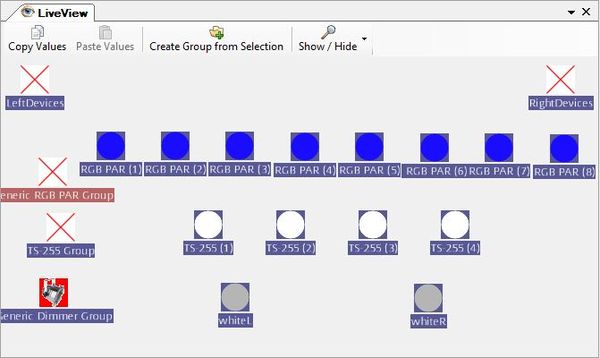
The stage view tool is one of the several tools in the tool menue. When you create devices and groups some (animated) icons are automatically generated in the stage view. You can shift these icon to a wanted place by mouse dragging. This way you can model your stage in 2D representation.
It could be helpful to load an background picture for better mapping your stage (right mouse context menue). Additional background pictures can be inserted in ".../DMMXControl3.0/Kernel/Pictures" folder.
It is possible to create several stage view panels that are administrated with the project explorer. In this way you can split your devices or map different locations for your show.
To add devices or device groups in a Stage View, let's move into the Project Explorer, drag and drop units into the respective Stage View.
The stage view distunguishes in "single lamp" icons and "group" icons. If you select an group icon all following operational actions are applied to each group member item.
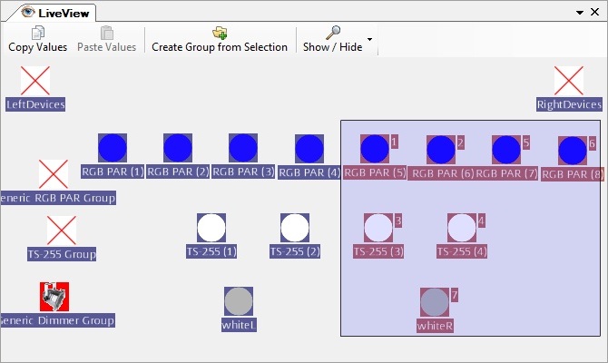
You can select a set of devices by drawing a frame around them (this is a kind of temporary group - please do not confuse this with the default groups) or by single selection holding the "CTRL" key. Marking such a set of device can also be helpful for positioning the icons. By "create group" button you can define permanent groups from the selection.
There are some helpful shortcuts helping to improve the assignment of icons in the liveview (moving and alignment of symbols). At first you have to select the device icons by drawing a frame or pressing the "STRG/CTRL" key (windows style selection).
| key | action | result |
|---|---|---|
| M ("Matrix") | press keys Shift+M and drag mouse | a matrix is created from the selected icons |
| F ("Fanning") | press keys Shift+F and drag mouse | icons are proportionally aligned (e.g. in a row) |
| C ("Circle") | press keys Shift+C and drag mouse | icons are aligned in shape of circle |
By using Show/Hide button can be set, which attributes to displayed for the icons.
Excercise
- Try to generate the same layout in the live view panel as shown above by shifting the icons
- Mark a subset of devices and take place an operation with property panels (below, press at first "Lumos" button in intensity panel)
Certificate
I have understood the topics of this lecture and want to continue with next course: Lesson 5

