If planning is inadequate, you might face the problem of not knowing whether a power circuit will be overloaded during the show. With the Electricity Management, DMXControl 3 provides virtual monitoring for this issue. You can create, label, and link your power circuits with your devices. If a circuit is overloaded, you will be notified by an alert lamp in the Softdesk, for example.
Overview
In the Electricity Management, you can set up various power circuits and assign them to the devices used in the project. It is also possible to create a hierarchy and define sub-distributions. A typical case would be a central power connection with sub-distributions and multiple power strips connected to those sub-distributions.
Each created power circuit is assigned a nominal current, which is set to 16 A (approximately 3,600 W) by default. However, the nominal current can be adjusted to match the fuse size. If a power circuit is overloaded, the system displays an "Overload" message.
| The displayed power consumption is only calculated by DMXControl 3! This means that the actual power consumption may differ from the displayed value. Therefore, the Electricity Management function should be considered a supporting tool only. To measure actual consumption, a suitable measuring device must be used. |
Usage
Setting up Electricity Management
Creating Power Circuits
First, the power circuits must be created. This configuration is done in the Project Explorer. Under the Electricity entry, new power circuits can be added via the context menu. These can be nested using Drag & Drop. There are no limits to the configuration. You can create a simple circuit breaker for all devices connected to a single outlet or define an entire sub-distribution with individual fuses, outlets, and power strips.
Assigning Devices
To assign a Device to a specific power circuit, drag and drop it from the Devices folder in the Project Explorer to the desired folder. For correct power calculation, you must specify the device's power consumption in its properties. There are two parameters:
- "Static Wattage": Represents the static power consumption.
- "Dimmer Wattage": Represents dynamic power consumption based on the dimmer channel level. Higher dimmer levels result in higher power consumption.
Note: Devices with mechanical dimmers only have static power consumption because the light source remains on continuously. This applies, for example, to moving heads with discharge lamps.
Display
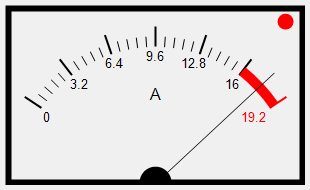
The current power consumption of the circuits is shown in the Electricity window, accessible via « Windows »⇒ « Electricity ». Each circuit's power consumption is displayed as a VU meter. If a circuit is overloaded (reaches the red zone), a red warning light will illuminate. Double-clicking a meter switches it to display the current power consumption.

|
| Figure 1: VU Meter overloaded by 10 % |
Overload notifications appear in the following areas:
- In the Electricity window, a red dot appears in the top-right corner of the VU meter for the overloaded circuit (see Figure 1).
- The GUI toolbar in the lower-right corner shows a VU meter icon.
- The Overload input in the Input Assignment is set to
True.
Using the Overload input, you can create logic in the Input Assignment to perform actions such as reducing the Grandmaster by 10% or starting another Cuelist.
CSV Export
Power circuits are also included in the CSV export. You can access this feature via the context menu of a selected device in the Project Explorer under « Patching and CSV Export ». In the window that opens, click the [CSV Export] button.
External Control
Information about theoretical electrical power consumption can be accessed through the Input Assignment using the following node:
